Introduction
This circuit is
designed for single phase ac motors. This is a very simple circuit.In this
circuit overload relay is used which protects the motor. The contactor is used
for interlocking and the push buttons are used to start the motor.
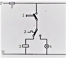
Apparatus
1 Press momentary switch
2 Electro thermic over current relay
3 Magnetic
contactor
4 Indicating lamp
Fuse
Explanation
In this circuit a single phase ac motor is connected to a
supply through a transmission line or from any source, the purpose of this
circuit is to protect the motor through a huge amount of current. The function
of this circuit takes place when an excess amount of current starts passing
through the circuit to motor. This circuit consists of a press momentary switch,
by pressing this switch the motor starts running. When a huge amount of current
comes through the circuit, the electro thermic overcurrent relay will sense the
excess amount of current and will send
the operating signal to the circuit breaker and the circuit breaker will
operate and close the circuit of the motor and the motor will stop running and
by this process the whole circuit will be tripped or stopped before the excess
amount of current start passing through the circuit.
Circuit Diagram
Uses
This circuit
is used in all the places where single
phase motor is used up to 6 hours
regularly.

